DC offset occurs when hardware, such as a sound card, adds DC current to a recorded audio signal. This current results in a recorded waveform that is not centered around the baseline. In some cases, when DC-Offset is present, glitches and other unexpected results can occur when sound effects are applied to the audio file. You can compensate for this DC offset by adding a constant value to the samples in the sound file.
An easy way to spot DC offset is to zoom in to a silent section. If the silent waveform matches the centerline in the waveform display, your file does not contain DC offset.
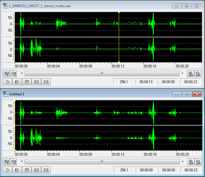
In the example above the upper waveform exhibits DC offset
To fix DC offset click “Process” -> “DC offset”. The following form will show up.
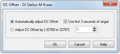
The first option ”Automatically adjust DC offset” option will search the entire audio stream to find if there is a DC component and if found the whole stream will be adjusted accordingly. If you check “Use first 3 seconds of signal” only the first 3 sec will be taken into account to calculate the CD component reducing the time to process.
The second option “Adjust DC offset by (-32768 to 32768) is a manual approach. You select the level of the DC offset to adjust the audio stream.
Technical Explanation
DC offset is an offsetting of a signal from zero. The term originated in electronics, where it refers to a direct current voltage, but the concept has been extended to any representation of a waveform. DC offset is the mean amplitude of the waveform; if the mean amplitude is zero, there is no DC offset.
DC offset is usually undesirable. For example, in audio processing, a sound that has DC offset will not be at its loudest possible volume when normalized (because the offset consumes headroom), and this problem can possibly extend to the mix as a whole, since a sound with DC offset and a sound without DC offset will have DC offset when mixed. It may also cause other artifacts depending on what is being done with the signal.
DC offset can be reduced in real-time by a one-pole one-zero high-pass filter. When one already has the entire waveform, subtracting the mean amplitude from each sample will remove the offset. Often, very low frequencies are called "slowly changing DC". While not technically accurate, a high pass filter can remove such a "changing offset" better because its cutoff does not extend to as low a bandwidth as the above method.
When describing a periodic function in the frequency domain, the term DC coefficient or DC component refers to the mean value of the waveform (possibly scaled according to the norm of the corresponding basis function of the frequency analysis filter bank). The name comes from the middle 20th century design of electrical line codes for use with transmission channels unable to transmit a DC voltage or current. In such usage, this coefficient represents the useless DC, whilst the coefficients representing various other frequencies are analogous to superimposed AC voltages or currents.
A waveform with a zero DC component is known as a DC-balanced waveform. DC-balanced waveforms are useful in communications systems, since they can be used on AC-coupled electrical connections to avoid voltage imbalance problems between connected systems or components. For this reason, most line codes are designed to produce DC-balanced waveforms. The most common classes of DC balanced line codes are constant-weight codes and paired-disparity codes.
|
Copyright (c) 2013 AudioDope team. All rights reserved.
|
|
What do you think about this topic? Send feedback!
|


